
Sitemap
A list of all the posts and pages found on the site. For you robots out there, there is an XML version available for digesting as well.
Pages
Posts
Future Blog Post
Published:
This post will show up by default. To disable scheduling of future posts, edit config.yml and set future: false.
Blog Post number 4
Published:
This is a sample blog post. Lorem ipsum I can’t remember the rest of lorem ipsum and don’t have an internet connection right now. Testing testing testing this blog post. Blog posts are cool.
Blog Post number 3
Published:
This is a sample blog post. Lorem ipsum I can’t remember the rest of lorem ipsum and don’t have an internet connection right now. Testing testing testing this blog post. Blog posts are cool.
Blog Post number 2
Published:
This is a sample blog post. Lorem ipsum I can’t remember the rest of lorem ipsum and don’t have an internet connection right now. Testing testing testing this blog post. Blog posts are cool.
Blog Post number 1
Published:
This is a sample blog post. Lorem ipsum I can’t remember the rest of lorem ipsum and don’t have an internet connection right now. Testing testing testing this blog post. Blog posts are cool.
portfolio
Industrial robotics & team leadership
<!doctype html><html lang="en"><head>
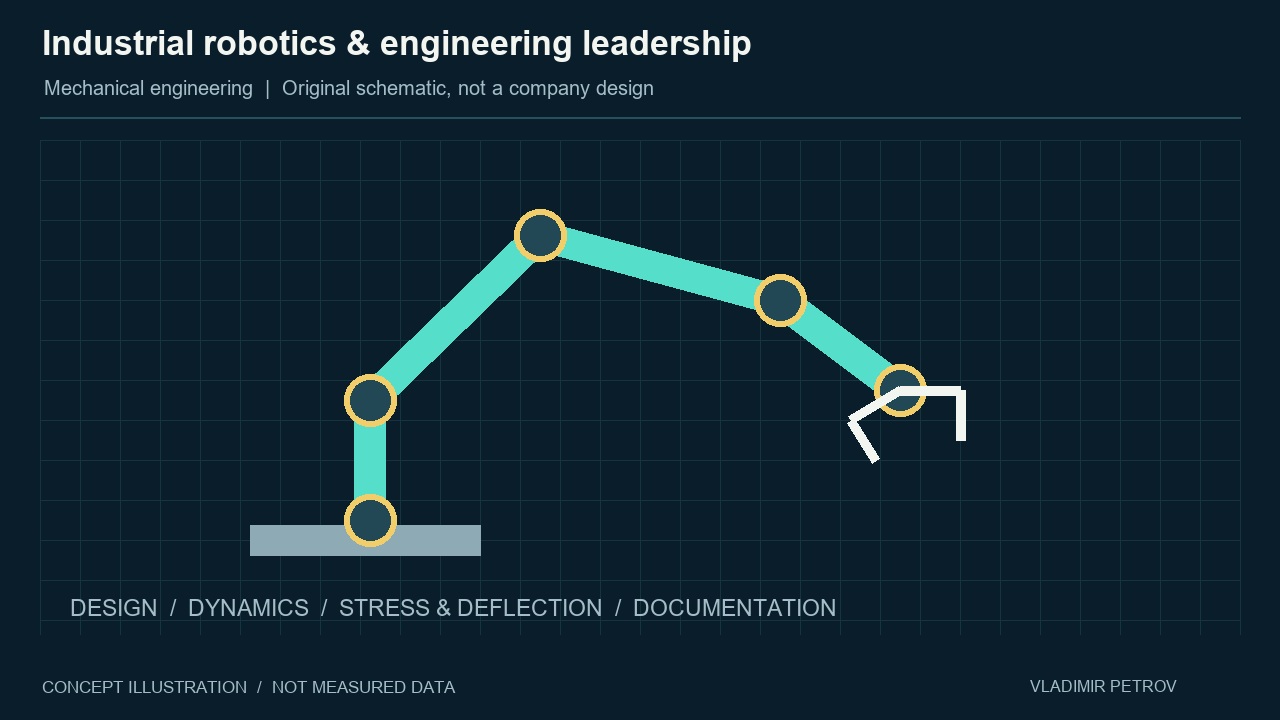 <figcaption>Original schematic · illustrative, not an employer’s product design.</figcaption>
Robot mechanisms & mechanical design
<!doctype html><html lang="en"><head>
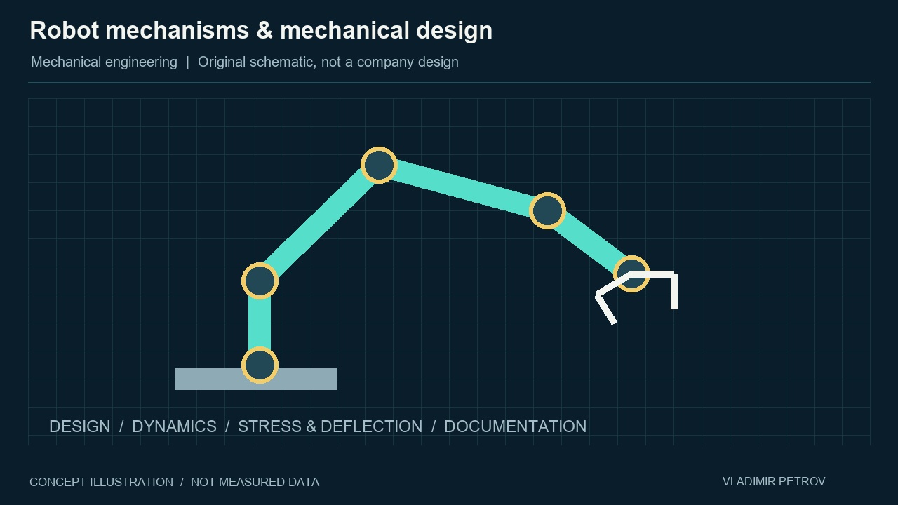 <figcaption>Original schematic · illustrative, not an employer’s product design.</figcaption>
Gantry & Delta robot development
<!doctype html><html lang="en"><head>
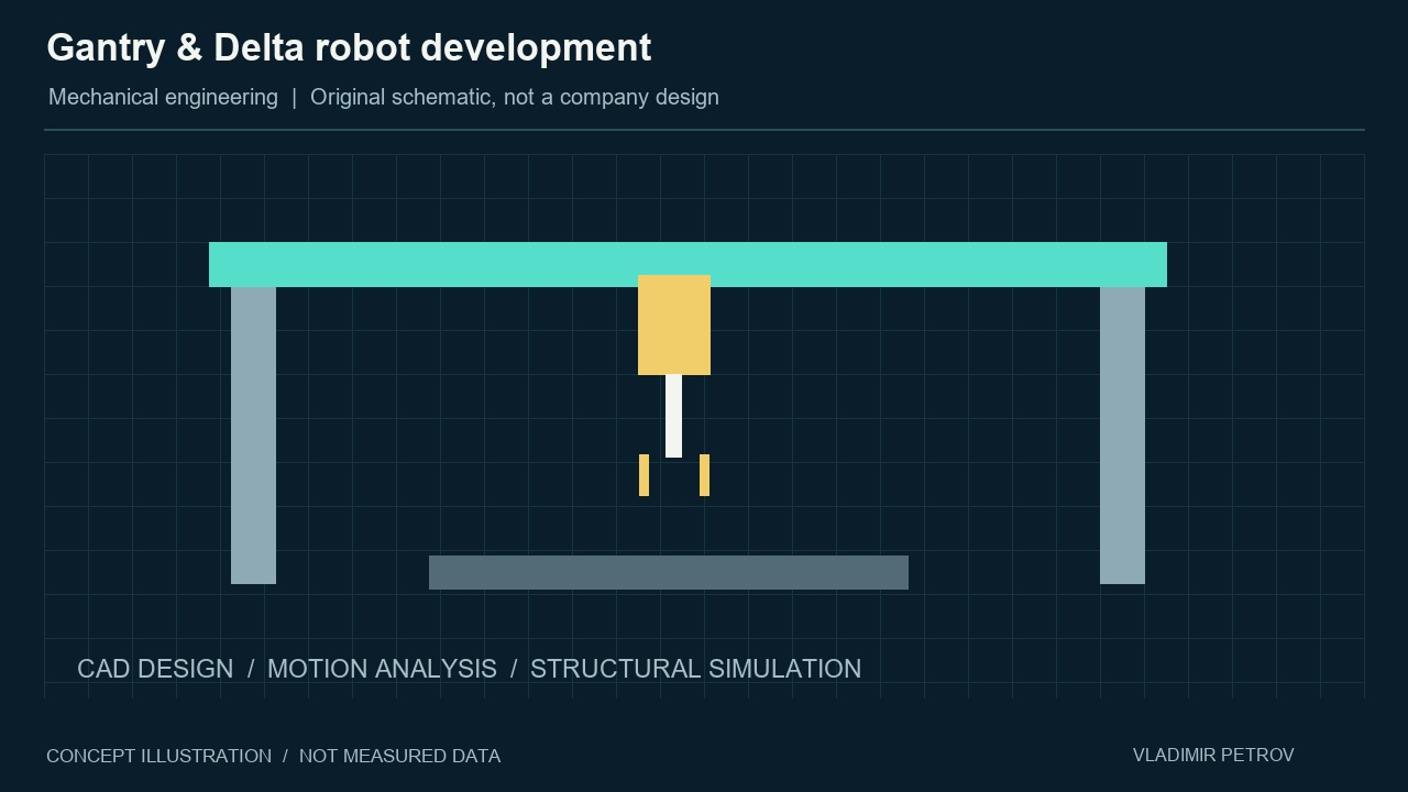 <figcaption>Original schematic · illustrative, not an employer’s product design.</figcaption>
Multi-drone inspection at MERL
<!doctype html><html lang="en"><head>
<summary>Visual description</summary><p>I configured SLAM Toolbox for independent localization, generated 2D maps for subsequent point-cloud representations, and ran RViz2 and hardware experiments. The diagram is an original mission illustration; it is not footage of the MERL experiment or an output of the paper’s planner.</p>
Flight under changing conditions
<!doctype html><html lang="en"><head>
<summary>Visual description</summary><p>Manuscript under review. The first video illustrates the sequence in three dimensions: nominal tracking, airflow, added mass, a moving virtual target and convergence. The trajectories are illustrative. The second video preserves the full supplied experiment, including RViz, position/heading plots and its existing 3× playback.</p>
Depth & heading control for AUVs
<!doctype html><html lang="en"><head>
<summary>Visual description</summary><p>The study is published in Ocean Engineering (2026), volume 368, article 128400. The detailed explainer covers model mismatch, adaptive reference management, physical actuator constraints, the choice of an infinite horizon, continuous-time domain transformation, Bernstein transcription into a nonlinear program, convex-hull geometry and the repeated MPC update. Method background: Fahroo and Ross (2008), for infinite-horizon domain transformation; Bernstein transcription is a separate step. The reported cases use calm water and a nonlinear six-degree-of-freedom simulation plant at two forward speeds. Animation traces are illustrative, not numerical results.</p>
<summary>Video chapters</summary><ol><li></li><li></li><li></li><li></li><li></li><li></li><li></li><li></li><li></li><li></li><li></li></ol>
<summary>Read the narration</summary><p>The mission
The vehicle must reach a commanded depth and heading while respecting the limits of its actuators. The side view shows depth and pitch; the top view shows heading. The study considers a nonlinear underwater vehicle controlled using reduced, linearized prediction models.</p><p>Why model mismatch matters
A linearized model makes repeated optimization practical, but it does not capture every nonlinear effect or coupling. In the studied baseline, this mismatch produces persistent depth and heading errors. This is a limitation of this baseline formulation, not of every possible predictive controller.</p><p>Give each layer a clear job
The adaptive reference layer adjusts the depth and heading references supplied to model predictive control. The predictive controller computes control inputs while incorporating state, actuator, and rate limits. Allocation converts the virtual control channels into commands for the physical control surfaces.</p><p>Make actuator limits visible
Each actuator has a permitted range and a limit on how quickly its command can change. The four tail planes combine vertical and horizontal control demands. The optimization accounts for their allocated commands, so a feasible virtual input must also respect the physical actuator bounds.</p><p>Designing MPC: why an infinite horizon?
Conventional model predictive control usually optimizes over a finite horizon. A short prediction window may end before the vehicle reaches its target. Here, an infinite horizon represents the full approach from the current state to the commanded final target, including settling.</p><p>Map time; the problem is still continuous
Following the infinite-horizon domain-transformation approach of Fahroo and Ross, we map physical time onto the interval from zero to one, excluding one. In our normalization, time equals tau divided by one minus tau. The transformed optimal control problem is still continuous in time; this mapping is not yet discretization.</p><p>Bernstein transcription: from OCP to NLP
Next, we choose approximation degree N and represent states and inputs with Bernstein polynomials. Their coefficients become optimization variables. Transcribing the cost, dynamics, and constraints produces a finite nonlinear program. Solving it determines the coefficients, and therefore the represented state and input trajectories.</p><p>Convex-hull containment at every degree
Bernstein basis functions are nonnegative and sum to one. The curve therefore stays inside the convex hull of its control points, even at a small degree N. Coefficient bounds in a convex admissible set bound the represented curve. Approximation accuracy remains a separate question.</p><p>Replan from new measurements
At each update, the controller uses the latest measured state to solve a new constrained prediction problem. It applies the current control input, receives fresh measurements, and repeats. The adaptive reference layer adjusts the targets used by this same predictive control structure.</p><p>Compare the same controller with and without augmentation
The manuscript compares predictive control alone with the same controller assisted by adaptive reference management. Model, costs, allocation, and constraints are retained to isolate the added layer. The reported simulations reduce steady-state depth and heading errors while respecting actuator magnitude and rate limits in the tested cases.</p><p>Interpret the evidence
The reported study uses a nonlinear simulation plant at two forward speeds, with calm-water test conditions. These animations illustrate the architecture and constraint geometry. They are not a replay of the simulation data, and they do not establish performance in arbitrary wave conditions.</p>
The vehicle must reach a commanded depth and heading while respecting the limits of its actuators. The side view shows depth and pitch; the top view shows heading. The study considers a nonlinear underwater vehicle controlled using reduced, linearized prediction models.</p><p>Why model mismatch matters
A linearized model makes repeated optimization practical, but it does not capture every nonlinear effect or coupling. In the studied baseline, this mismatch produces persistent depth and heading errors. This is a limitation of this baseline formulation, not of every possible predictive controller.</p><p>Give each layer a clear job
The adaptive reference layer adjusts the depth and heading references supplied to model predictive control. The predictive controller computes control inputs while incorporating state, actuator, and rate limits. Allocation converts the virtual control channels into commands for the physical control surfaces.</p><p>Make actuator limits visible
Each actuator has a permitted range and a limit on how quickly its command can change. The four tail planes combine vertical and horizontal control demands. The optimization accounts for their allocated commands, so a feasible virtual input must also respect the physical actuator bounds.</p><p>Designing MPC: why an infinite horizon?
Conventional model predictive control usually optimizes over a finite horizon. A short prediction window may end before the vehicle reaches its target. Here, an infinite horizon represents the full approach from the current state to the commanded final target, including settling.</p><p>Map time; the problem is still continuous
Following the infinite-horizon domain-transformation approach of Fahroo and Ross, we map physical time onto the interval from zero to one, excluding one. In our normalization, time equals tau divided by one minus tau. The transformed optimal control problem is still continuous in time; this mapping is not yet discretization.</p><p>Bernstein transcription: from OCP to NLP
Next, we choose approximation degree N and represent states and inputs with Bernstein polynomials. Their coefficients become optimization variables. Transcribing the cost, dynamics, and constraints produces a finite nonlinear program. Solving it determines the coefficients, and therefore the represented state and input trajectories.</p><p>Convex-hull containment at every degree
Bernstein basis functions are nonnegative and sum to one. The curve therefore stays inside the convex hull of its control points, even at a small degree N. Coefficient bounds in a convex admissible set bound the represented curve. Approximation accuracy remains a separate question.</p><p>Replan from new measurements
At each update, the controller uses the latest measured state to solve a new constrained prediction problem. It applies the current control input, receives fresh measurements, and repeats. The adaptive reference layer adjusts the targets used by this same predictive control structure.</p><p>Compare the same controller with and without augmentation
The manuscript compares predictive control alone with the same controller assisted by adaptive reference management. Model, costs, allocation, and constraints are retained to isolate the added layer. The reported simulations reduce steady-state depth and heading errors while respecting actuator magnitude and rate limits in the tested cases.</p><p>Interpret the evidence
The reported study uses a nonlinear simulation plant at two forward speeds, with calm-water test conditions. These animations illustrate the architecture and constraint geometry. They are not a replay of the simulation data, and they do not establish performance in arbitrary wave conditions.</p>
Depth & pitch control near the surface
<!doctype html><html lang="en"><head>
<summary>Visual description</summary><p>The published studies use numerical simulations. This detailed explainer introduces the near-surface problem, separates slow tracking error from wave-frequency actuator activity, explains the architecture, and compares the roles of nominal LQR, frequency shaping and L1 reference augmentation. Its motion and traces are illustrative, not paper data.</p>
<summary>Video chapters</summary><ol><li></li><li></li><li></li><li></li><li></li><li></li><li></li><li></li></ol>
<summary>Read the narration</summary><p>The mission
An underwater vehicle must follow a depth command close to the surface. Waves disturb its motion, while uncertain hydrodynamics can shift its average depth. The aim is accurate mean tracking without asking the actuators to fight every wave.</p><p>Two different problems
With a nominal regulator, the vehicle can remain offset from the commanded depth. At the same time, the control surfaces may react repeatedly to wave-driven motion. The two plots distinguish a persistent tracking error from unnecessary high-frequency control activity.</p><p>A layered solution
The commanded depth enters an adaptive reference layer. The LQR autopilot follows that adjusted reference and manages the actuators. Measurements return to both layers. The adaptive layer addresses slow uncertainty, while the regulator shapes the vehicle response.</p><p>Do not chase every wave
The regulator is designed using an augmented model with frequency weighting. Control activity around the wave frequency receives an additional penalty. This is built into the LQR design. It is not simply a filter added after an already designed controller.</p><p>Correct the mean tracking error
The adaptive layer estimates the effect of uncertainty and changes the reference supplied to the autopilot. The original command stays fixed. As the internal reference adjusts, the mean vehicle depth approaches the command, while residual wave-driven motion may remain.</p><p>The actuators tell the other half
A new depth command requires a real maneuver. Tail planes, the sail plane, and the hover tank contribute according to the control allocation. The desired outcome is reduced rapid actuator motion, not motionless actuators: they still respond to slower changes.</p><p>Compare the contributions
Compare the same maneuver in three configurations. Nominal LQR can exhibit offset and wave-frequency activity. Frequency shaping reduces the rapid control oscillations. Adding adaptive reference management addresses the remaining mean error. These animation traces explain the mechanisms; they are not numerical results.</p><p>What the published study establishes
The published work evaluates the approach with a Joubert BB2 simulation model. Its central idea is a division of responsibilities: frequency-shaped regulation manages wave-related actuator activity, and adaptive augmentation addresses slow disturbances and uncertainty. Quantitative results are available in the linked papers.</p>
An underwater vehicle must follow a depth command close to the surface. Waves disturb its motion, while uncertain hydrodynamics can shift its average depth. The aim is accurate mean tracking without asking the actuators to fight every wave.</p><p>Two different problems
With a nominal regulator, the vehicle can remain offset from the commanded depth. At the same time, the control surfaces may react repeatedly to wave-driven motion. The two plots distinguish a persistent tracking error from unnecessary high-frequency control activity.</p><p>A layered solution
The commanded depth enters an adaptive reference layer. The LQR autopilot follows that adjusted reference and manages the actuators. Measurements return to both layers. The adaptive layer addresses slow uncertainty, while the regulator shapes the vehicle response.</p><p>Do not chase every wave
The regulator is designed using an augmented model with frequency weighting. Control activity around the wave frequency receives an additional penalty. This is built into the LQR design. It is not simply a filter added after an already designed controller.</p><p>Correct the mean tracking error
The adaptive layer estimates the effect of uncertainty and changes the reference supplied to the autopilot. The original command stays fixed. As the internal reference adjusts, the mean vehicle depth approaches the command, while residual wave-driven motion may remain.</p><p>The actuators tell the other half
A new depth command requires a real maneuver. Tail planes, the sail plane, and the hover tank contribute according to the control allocation. The desired outcome is reduced rapid actuator motion, not motionless actuators: they still respond to slower changes.</p><p>Compare the contributions
Compare the same maneuver in three configurations. Nominal LQR can exhibit offset and wave-frequency activity. Frequency shaping reduces the rapid control oscillations. Adding adaptive reference management addresses the remaining mean error. These animation traces explain the mechanisms; they are not numerical results.</p><p>What the published study establishes
The published work evaluates the approach with a Joubert BB2 simulation model. Its central idea is a division of responsibilities: frequency-shaped regulation manages wave-related actuator activity, and adaptive augmentation addresses slow disturbances and uncertainty. Quantitative results are available in the linked papers.</p>
Learning a dynamics correction for MPC
<!doctype html><html lang="en"><head>
<summary>Visual description</summary><p>Research in development. The detailed video explains model mismatch, learning during operation, validation, the conditional handover and a subsequent command. No successful closed-loop handover is claimed. Any reduction in energy consumption or computation would require measurement; it is not assumed from switching off an adaptive layer.</p>
<summary>Video chapters</summary><ol><li></li><li></li><li></li><li></li><li></li><li></li><li></li><li></li></ol>
<summary>Read the narration</summary><p>A different research question
Adaptive support can compensate for model mismatch while the vehicle operates. The next question is whether the system can learn a reusable description of that mismatch. The objective is to improve prediction and reduce reliance on continuous adaptive compensation, rather than claim an unmeasured energy saving.</p><p>The source of the prediction error
Model predictive control uses linearized dynamics to predict the vehicle response. Measurements reveal effects that this nominal model misses. The gap between predicted and observed dynamics supplies information for learning. The network aims to describe that residual, rather than replace the entire controller.</p><p>Operate with support while collecting experience
Initially, adaptive reference management and predictive control operate together. As the underwater vehicle follows commands, measurements and applied inputs provide learning data. The adaptive layer remains active during this stage, helping control the vehicle while the network learns from its experience.</p><p>Learn a correction, not a second control command
The learning network estimates a correction to the nominal dynamics. That correction is intended for use inside the predictive model. It is not a separate actuator command added to the output. The scene shows the intended reduction of model mismatch, not a measured training curve.</p><p>Check the correction before switching
Learning alone is not enough to justify a handover. The correction must be checked on relevant conditions, and its effect on tracking and constraints must be assessed. Adaptive support stays available until those checks justify the transition. A training loss by itself is not proof of closed-loop reliability.</p><p>The intended handover
After validation, the intended transition disables the adaptive reference contribution. The learned dynamics correction remains inside model predictive control. The optimization structure and actuator limits are retained. This is the research handover being investigated, not a claim that the network has learned every possible condition.</p><p>A new command after handover
A new depth and heading command tests the post-handover configuration. Predictive control uses the nominal model plus the learned correction. Tracking, constraint compliance, and sensitivity to unfamiliar conditions must all be evaluated. The motion here illustrates the intended behavior rather than a validated experiment.</p><p>What success would mean
The expected value is retained model knowledge and less dependence on continuous adaptive correction within validated conditions. Whether this also saves computation or electrical energy requires measurement: network inference and optimization have costs of their own. This project remains a research concept under development.</p>
Adaptive support can compensate for model mismatch while the vehicle operates. The next question is whether the system can learn a reusable description of that mismatch. The objective is to improve prediction and reduce reliance on continuous adaptive compensation, rather than claim an unmeasured energy saving.</p><p>The source of the prediction error
Model predictive control uses linearized dynamics to predict the vehicle response. Measurements reveal effects that this nominal model misses. The gap between predicted and observed dynamics supplies information for learning. The network aims to describe that residual, rather than replace the entire controller.</p><p>Operate with support while collecting experience
Initially, adaptive reference management and predictive control operate together. As the underwater vehicle follows commands, measurements and applied inputs provide learning data. The adaptive layer remains active during this stage, helping control the vehicle while the network learns from its experience.</p><p>Learn a correction, not a second control command
The learning network estimates a correction to the nominal dynamics. That correction is intended for use inside the predictive model. It is not a separate actuator command added to the output. The scene shows the intended reduction of model mismatch, not a measured training curve.</p><p>Check the correction before switching
Learning alone is not enough to justify a handover. The correction must be checked on relevant conditions, and its effect on tracking and constraints must be assessed. Adaptive support stays available until those checks justify the transition. A training loss by itself is not proof of closed-loop reliability.</p><p>The intended handover
After validation, the intended transition disables the adaptive reference contribution. The learned dynamics correction remains inside model predictive control. The optimization structure and actuator limits are retained. This is the research handover being investigated, not a claim that the network has learned every possible condition.</p><p>A new command after handover
A new depth and heading command tests the post-handover configuration. Predictive control uses the nominal model plus the learned correction. Tracking, constraint compliance, and sensitivity to unfamiliar conditions must all be evaluated. The motion here illustrates the intended behavior rather than a validated experiment.</p><p>What success would mean
The expected value is retained model knowledge and less dependence on continuous adaptive correction within validated conditions. Whether this also saves computation or electrical energy requires measurement: network inference and optimization have costs of their own. This project remains a research concept under development.</p>
A planner for constrained flight
<!doctype html><html lang="en"><head>
<summary>Visual description</summary><p>Accepted for AIAA SciTech in January 2027. The first video is a qualitative 3D illustration, not an output of the research planner. The second is the supplied experiment with all camera and visualization panels retained. Technical details will accompany the publication.</p>
Offline RL tuning for AUV control
<!doctype html><html lang="en"><head>
<summary>Visual description</summary><p>Research in development. The detailed video explains the tuning variables, the reset–trial–evaluation cycle, response trade-offs and use of selected settings. It does not report a trained policy, measured improvement, global optimality or guaranteed zero overshoot.</p>
<summary>Video chapters</summary><ol><li></li><li></li><li></li><li></li><li></li><li></li><li></li><li></li></ol>
<summary>Read the narration</summary><p>The tuning problem
A working controller still needs suitable parameters. An aggressive response can overshoot, while a conservative response may settle slowly. This project explores reinforcement learning to tune the adaptive reference dynamics before deployment, balancing tracking behavior and control effort for underwater maneuvers.</p><p>Where reinforcement learning acts
The control architecture contains adaptive reference management followed by model predictive control. Reinforcement learning acts on selected tuning parameters of the adaptive layer. It does not replace the predictive controller, and it does not issue new actuator commands at every control step.</p><p>Two natural frequencies to select
The tuning variables are the natural frequencies of the desired depth and heading reference dynamics. Changing them shapes the requested transient response. Their effects must be evaluated in the complete closed loop, because faster desired dynamics do not automatically produce less overshoot or better performance.</p><p>One candidate, one complete trial
Before each simulation episode, the agent chooses a candidate pair of frequencies. The simulation is reset and a complete maneuver is evaluated. That parameter pair stays fixed throughout the episode. The trial response then informs the next offline choice.</p><p>Evaluate the trade-offs
Each response is assessed for tracking error, overshoot, settling behavior, and control effort. A useful candidate balances these objectives rather than improving one by making another unacceptable. The illustrative comparison shows why the fastest-looking initial response need not be the preferred tuning.</p><p>Choose and check a candidate
Offline learning searches for a useful parameter set within the considered domain. A selected candidate then needs validation on representative commands and conditions. The aim is better tuning for those cases, not proof of a globally ideal setting or a universal guarantee of zero overshoot.</p><p>Use the settings during the maneuver
The selected frequencies are loaded into the adaptive reference layer. During operation, those tuning values remain fixed while the controller responds to new depth and heading commands. Adaptive compensation can still evolve with measurements; fixed tuning does not mean that the adaptive layer is switched off.</p><p>What this project would establish
The final comparison should use the original and learned tuning under the same conditions, measuring overshoot, settling time, tracking error, and control effort. This preview explains that workflow. It does not present trained-policy results or measured improvement, because the research is still in development.</p>
A working controller still needs suitable parameters. An aggressive response can overshoot, while a conservative response may settle slowly. This project explores reinforcement learning to tune the adaptive reference dynamics before deployment, balancing tracking behavior and control effort for underwater maneuvers.</p><p>Where reinforcement learning acts
The control architecture contains adaptive reference management followed by model predictive control. Reinforcement learning acts on selected tuning parameters of the adaptive layer. It does not replace the predictive controller, and it does not issue new actuator commands at every control step.</p><p>Two natural frequencies to select
The tuning variables are the natural frequencies of the desired depth and heading reference dynamics. Changing them shapes the requested transient response. Their effects must be evaluated in the complete closed loop, because faster desired dynamics do not automatically produce less overshoot or better performance.</p><p>One candidate, one complete trial
Before each simulation episode, the agent chooses a candidate pair of frequencies. The simulation is reset and a complete maneuver is evaluated. That parameter pair stays fixed throughout the episode. The trial response then informs the next offline choice.</p><p>Evaluate the trade-offs
Each response is assessed for tracking error, overshoot, settling behavior, and control effort. A useful candidate balances these objectives rather than improving one by making another unacceptable. The illustrative comparison shows why the fastest-looking initial response need not be the preferred tuning.</p><p>Choose and check a candidate
Offline learning searches for a useful parameter set within the considered domain. A selected candidate then needs validation on representative commands and conditions. The aim is better tuning for those cases, not proof of a globally ideal setting or a universal guarantee of zero overshoot.</p><p>Use the settings during the maneuver
The selected frequencies are loaded into the adaptive reference layer. During operation, those tuning values remain fixed while the controller responds to new depth and heading commands. Adaptive compensation can still evolve with measurements; fixed tuning does not mean that the adaptive layer is switched off.</p><p>What this project would establish
The final comparison should use the original and learned tuning under the same conditions, measuring overshoot, settling time, tracking error, and control effort. This preview explains that workflow. It does not present trained-policy results or measured improvement, because the research is still in development.</p>
publications
Paper Title Number 1
Published in Journal 1, 2009
This paper is about the number 1. The number 2 is left for future work.
Recommended citation: Your Name, You. (2009). "Paper Title Number 1." Journal 1. 1(1).
Download Paper | Download Slides | Download Bibtex
Paper Title Number 2
Published in Journal 1, 2010
This paper is about the number 2. The number 3 is left for future work.
Recommended citation: Your Name, You. (2010). "Paper Title Number 2." Journal 1. 1(2).
Download Paper | Download Slides
Paper Title Number 3
Published in Journal 1, 2015
This paper is about the number 3. The number 4 is left for future work.
Recommended citation: Your Name, You. (2015). "Paper Title Number 3." Journal 1. 1(3).
Download Paper | Download Slides
Paper Title Number 4
Published in GitHub Journal of Bugs, 2024
This paper is about fixing template issue #693.
Recommended citation: Your Name, You. (2024). "Paper Title Number 3." GitHub Journal of Bugs. 1(3).
Download Paper
talks
Robotics Lab Demonstration for Top Scholars Visit Day
Published:
Presented robotics research and laboratory demonstrations for visiting high school students as part of the University of Iowa Top Scholars Visit Day. The demonstration introduced autonomous systems, robotics experiments, and the role of undergraduate students in robotics research.
Autonomous Systems and Control Research Presentation
Published:
Presented research related to autonomous systems, robotics, control, trajectory planning, and experimental validation at CAMS 2024, held at Virginia Tech from September 3–5, 2024.
Robotics Laboratory Open Doors Demonstration
Published:
Presented robotics laboratory demonstrations to invited guests and visitors, highlighting ongoing research in autonomous systems, drone control, motion planning, and experimental robotics.
Bernstein Polynomial-Based Adaptive Model Predictive Planning for Crazyflie UAVs
Published:
Conference presentation at the AIAA SciTech 2026 Forum, held January 12–16, 2026, in Orlando, Florida.
Robotics Demonstration for Middle School Students
Published:
Presented an educational robotics demonstration for middle school students, introducing autonomous systems, drones, robotics research, and engineering concepts through laboratory examples.
Crazyflie Control Demonstrations for Research Sponsors, Faculty, and Student Visitors
Published:
Presented two separate robotics demonstrations: one for research sponsors and faculty visitors focused, and another for middle school students interested in robotics and autonomous systems.
Robotics Lab Demonstration for Top Scholars Visit Day
Published:
Presented robotics research and laboratory demonstrations for visiting high school students as part of the University of Iowa Top Scholars Visit Day. The demonstration introduced autonomous systems, drone experiments, robotics research, and opportunities for undergraduate involvement in the lab.
teaching
Teaching experience 1
Undergraduate course, University 1, DepartmeNt, 2014
This is a description of a teaching experience. You can use markdown like any other post.
Teaching experience 2
Workshop, University 1, Department, 2015
This is a description of a teaching experience. You can use markdown like any other post.